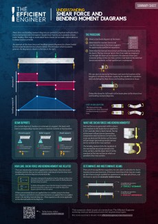
Shear force and bending moment diagrams are powerful graphical methods that are used to analyze a beam under loading. This page will walk you through what shear forces and bending moments are, why they are useful, the procedure for drawing the diagrams and some other keys aspects as well.
If you’re not in the mood for reading, just watch the video!
What Are Shear Forces and Bending Moments?
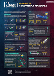
When loads are applied to a beam, internal forces develop within the beam in response to the loads. We can visualise these forces by making an imaginary cut through the beam and considering the internal forces acting on the cross-section. These internal forces have two components:
- Shear forces, that are oriented in the vertical direction, parallel to the beam cross-section
- Normal forces, that are oriented along the axis of the beam, perpendicular to the beam cross-section
The internal forces develop in such a way as to maintain equilibrium. No matter where the imaginary cut is made along the length of the beam, the effect of the internal forces will always balance the effect of the external forces.
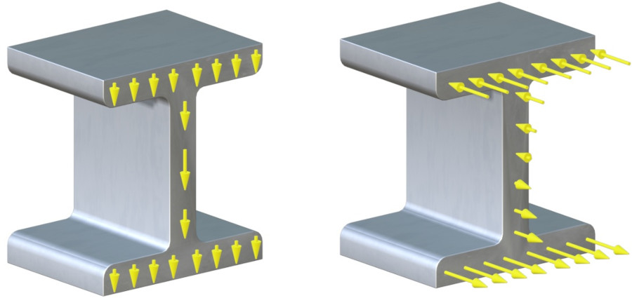
The normal stresses will be tensile on one side of the cross-section, and compressive on the other. If the beam is sagging the top of the beam will get shorter, and so the normal forces acting at the top will be compressive. The bottom of the beam will get longer, and so the normal forces acting at the bottom of the beam will be tensile.
These forces cancel each other out so they don’t produce a net force perpendicular to the beam cross-section, but they do produce a moment.
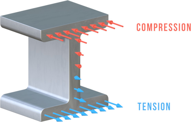
This means that the internal forces acting on the cross-section of the beam can be represented by one resultant force, called a shear force, that is the resultant of the internal shear forces, and by one resultant moment, called a bending moment, that is the resultant of the internal normal forces.
Why Are Shear Force and Bending Moment Diagrams Useful?
Shear force and bending moment diagrams are used to analyse and design beams. By showing how the shear force and bending moment vary along the length of a beam, they allow the loading on the beam to be quantified.
They are often used as a starting point for performing more detailed analysis, which might include calculating stresses in beams or determining how beams will deflect.
The Efficient Engineer Summary Sheets
The Efficient Engineer summary sheets are designed to present all of the key information you need to know about a particular topic on a single page. It doesn’t get more efficient than that!
Beam Loads and Supports
The shear forces and bending moments along a beam do not depend on the geometry of the beam cross-section or the material the beam is made of. They depend on two factors only:
- How the beam is loaded
- How the beam is supported
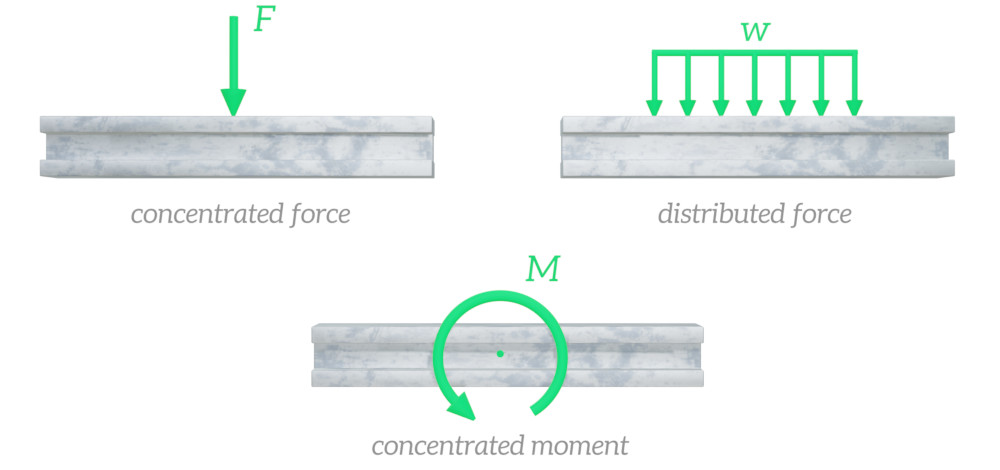
Let’s look at loads first. The most common ways of applying loads to a beam are concentrated forces, distributed forces, and concentrated moments. Distributed forces can be uniform, or non-uniform.
In the real world beams can be supported in many different ways, but for analysis purposes real supports can be modelled as one of three idealised supports – pinned supports, roller supports and fixed supports. Each of these supports restrains the beam in different ways.

- vertical displacement
- horizontal displacement
- rotation

- vertical displacement
- horizontal displacement
- rotation
- vertical displacement
- horizontal displacement
- rotation
When a certain degree of freedom (rotation or translation) is restrained at a support, there will be a corresponding reaction force or reaction moment at that location. At a pinned support for example a beam will be experiencing horizontal and vertical reaction forces, because horizontal and vertical displacements are restrained, but there will be no reaction moment because the beam can rotate at the pinned support.
A free body diagram is a simple sketch that shows all of the external loads acting on a beam and any reaction forces from supports. Figuring out the free body diagram is an important first step in determining the shear force and bending moment diagrams.
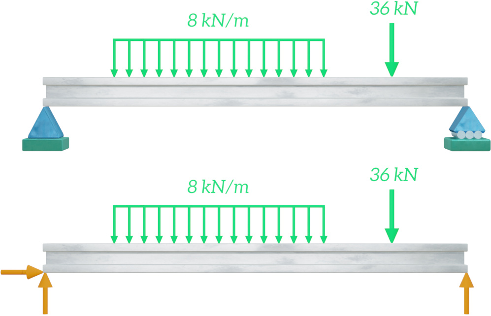
Consider the pinned support in the beam configuration shown above. The beam can rotate at this support, so there is no reaction moment, but displacements in the vertical and horizontal directions are prevented, so there will be horizontal and vertical reaction forces. At the roller support there is just a vertical reaction force. These three reaction forces and the applied distributed and concentrated forces are shown on the free body diagram.
What is the reaction moment at the fixed support for the cantilever beam configuration shown in the image below?
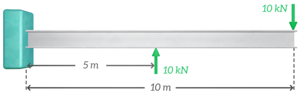
0 kNm
-50 kNm
-100 kNm
25 kNm
To ensure static equilibrium, the reaction moment at the fixed support must be equal and opposite to the sum of the external moments acting about that point.
$$M = 5 \cdot 10 - 10 \cdot 10 = -50\,\,\mathrm{kNm}$$
How To Draw the Shear Force and Bending Moment Diagram
There are three main steps that need to be followed to determine the shear force and bending moment diagrams:
Although the external loads are known, the reaction forces and moments at the supports are not – they need to be calculated. This can be done by considering the fact that all of the external loads, both the applied loads and the loads at the supports, must balance each other. If they didn’t the beam would not be in static equilibrium.
This can be represented by three equilibrium equations. These equations state that the sum of the forces in the horizontal direction, the sum of the forces in the vertical direction, and the sum of the moments taken about any point must all be equal to zero. $$\sum{F_x} = 0$$ $$\sum{F_y} = 0$$ $$\sum{M} = 0$$
The reaction forces and moments at the supports can be calculated using these equations.
We now have all the information needed to determine the shear force and bending moment diagrams.
As mentioned in an earlier part of this article, if we make an imaginary cut through the beam at any location, the internal forces and moments acting on the cut cross-section must balance the external forces and moments. This means that we can once again apply the equilibrium equations to calculate the shear forces and bending moments along the beam.

Start at one end of the beam and move the location of the imaginary cut to the other end, applying the equilibrium equations and calculating the shear forces and bending moments as you move along the beam.
Doing this along the full length of the beam will give you the shear force and bending moment diagrams.
Sign Conventions
A consistent sign convention needs to be used when calculating shear forces and bending moments. The most common sign convention is as follows:
- Applied forces are positive if they are acting in the downwards direction.
- If the beam is on the left side of the imaginary cutting plane shear forces pointing downwards are positive. If the beam is on the right side of the cutting plane, shear forces pointing upwards are positive.
- If a bending moment causes sagging then it is positive, and if it causes hogging then it is negative.
These sign conventions are summarised in the figure below.

Let’s work through an example to show the process of determining the shear force and bending moment diagrams from start to finish.
Example - Simply Supported BeamIn this example we’ll determine the shear force and bending moment diagram for a simply supported beam that is carrying two loads.
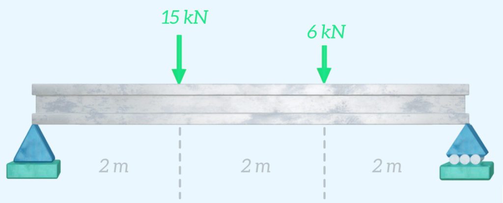
The first step is drawing the free body diagram. There are horizontal and vertical reaction forces at the pinned support (Point A) and a there is one vertical reaction force at the roller support (Point B).
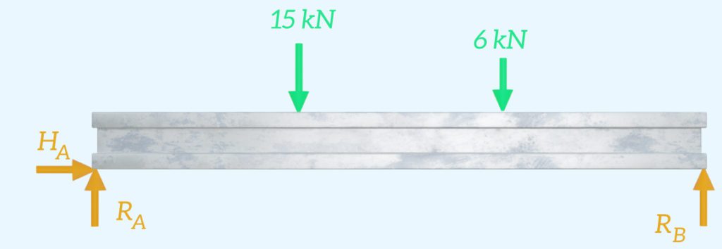
Next we need to apply the equilibrium equations to determine the unknown reaction forces at Point A and Point B. The sum of the forces in the horizontal direction must be zero. $H_A$ is the only force in the horizontal direction, so it must be equal to zero:
$$\sum{F_x} = 0$$
$$H_A = 0 \mathrm{kN}$$
The sum of the forces in the vertical direction must be equal to zero:
$$\sum{F_y} = 0$$
$$R_B + R_A = 15 + 6$$
And the sum of the moments about any point must be equal to zero. If we choose to take the moments about Point B we get the following:
$$\sum{M_B} = 0$$
$$(-R_A \cdot 6) + (15 \cdot 4) + (6 \cdot 2) = 0$$
We can solve this equation to determine that:
$$R_A = 12 \mathrm{kN}$$
Substituting $R_A$ into the vertical equilibrium equation gives:
$$R_B + 12 = 15 + 6$$
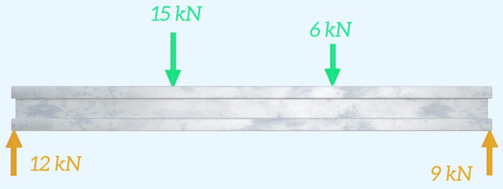
$$R_B = 9 \mathrm{kN}$$
All of the external loads acting on the beam have now been determined, and the free body diagram can be updated.
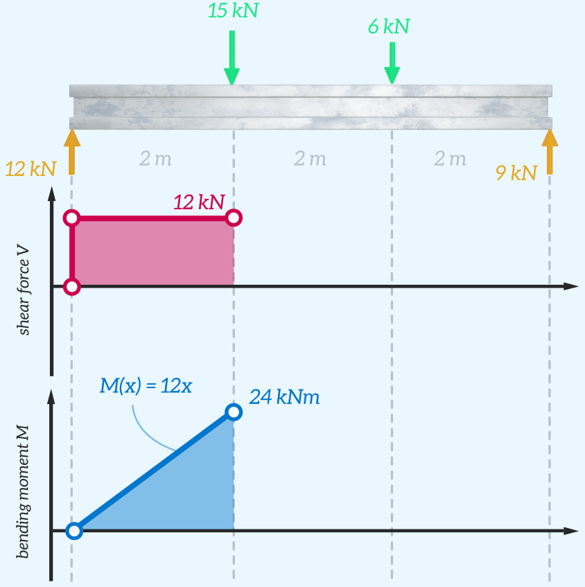
Now we can start to draw the shear force and bending moment diagrams, starting from the left side of the beam. We can draw the free body diagram showing a beam segment which has been cut immediately the right of the 12 kN reaction force at Point A.

To maintain equilibrium, the shear force V(x) must balance the 12 kN reaction force:
$$V(x) = 12 \mathrm{kN}$$
Similarly, the bending moment must balance the moment generated by the 12 kN reaction load:
$$M(x) = 12x$$

The shear force will be constant until we reach the next applied force, so we can draw this on shear force diagram. And the equation obtained for M(x) is the equation for a straight line, which can be drawn on the bending moment diagram.
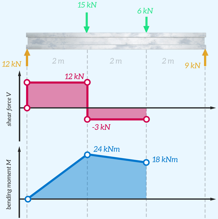
The process is then repeated, moving the location of the imaginary cut further to the right. This time the cut is placed immediately after the 15 kN force, and the free body diagram is drawn. The shear force and bending moment can be calculated by applying the equilibrium equations.
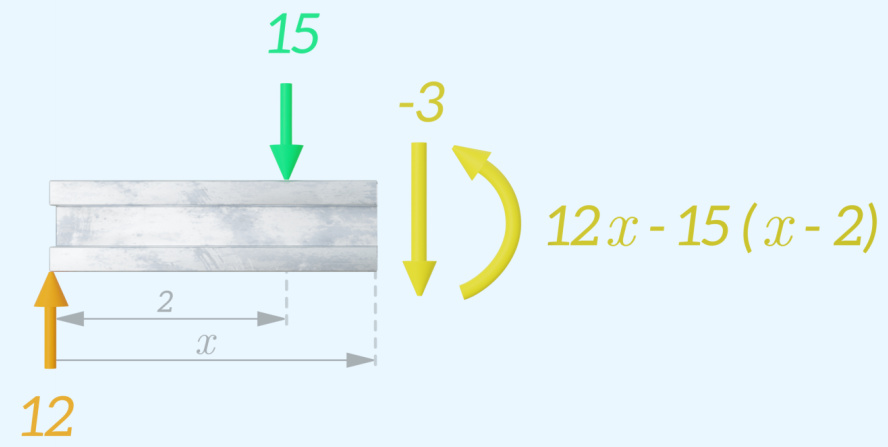
The shear force and bending moment diagrams can be updated.
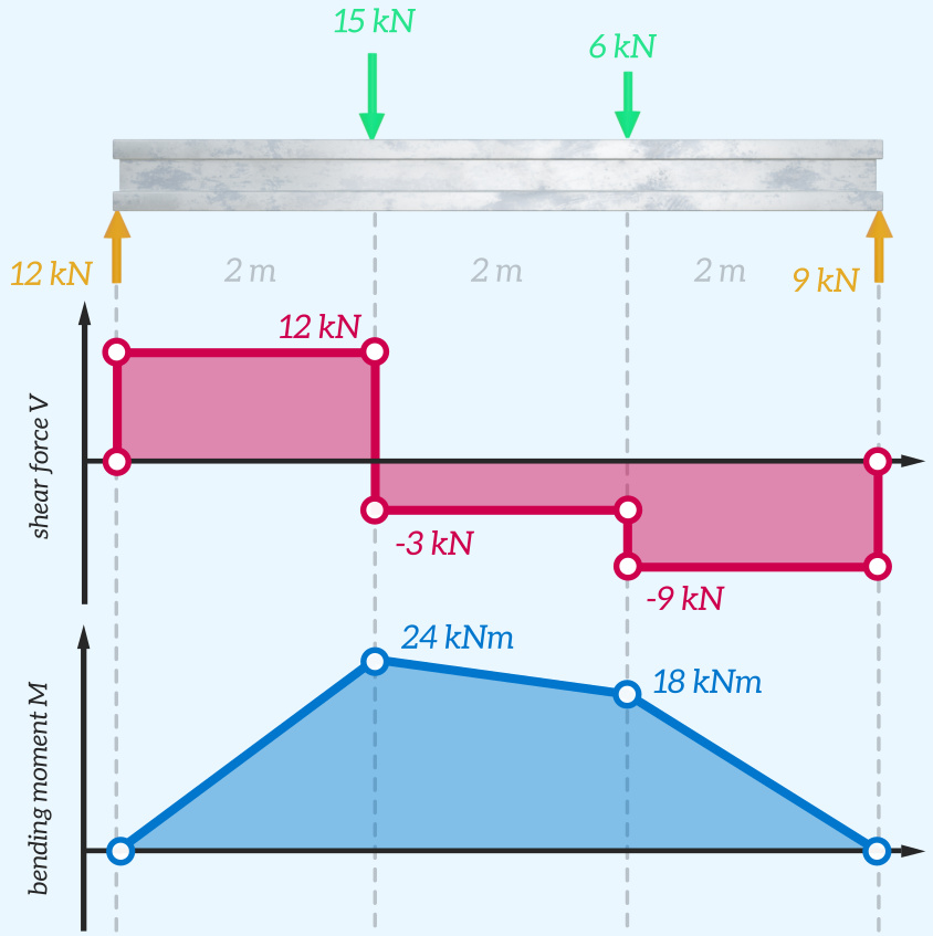
This process is repeated until the full length of the beam has been covered. The completed diagrams are shown below.
Related Topics
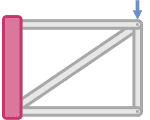
Trusses
Trusses are structures (e.g bridges or roofs) made up of members that can only carry tensile or compressive axial loads.
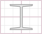
Area Moment of Inertia
The area moment of inertia describes how the material of a cross-section is distributed relative to a specific bending axis.