Trusses are important structures in engineering that are used in all sorts of applications, from bridges and roofs to parts of the International Space Station. The reason they are so useful is that they allow us to create strong and rigid structures while using materials in a very efficient way.
This page will cover everything you need to know to understand and analyse trusses, but you can also watch the video below for the animated version!
What is a truss?
A truss in everyday language is a rigid structure that is made up of a collection of straight members. But in an engineering and strength of materials context it has a more specific meaning – in these contexts a truss is a structure made up of members that only carry axial loads.
The members of a structure can be considered to only carry axial loads if the following assumptions are applicable:
The joints of the structure behave like pinned connections
Loads are only applied at the joints of the structure
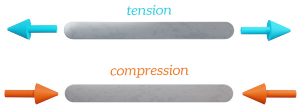
If these assumptions can be applied, the truss members are not acted on by any bending moments – they only carry axial loads. This means that each member of a truss must be either in tension or in compression.
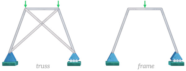
The fact that truss members only carry axial loads makes the analysis of trusses much easier than the analysis of frames, for example, where the members can carry both bending moments and axial loads.
When can a structure be analysed as a truss?
Few real structures have actual pinned connections, so how do you decide if you can analyse a real structure as a truss?
The members of real structures like bridges are often rigidly connected using what is known as a gusset plate, a plate that is bolted or riveted to several structural members, as shown in the photograph below. If the centre-lines of all of the members at a joint intersect at the same point, then it is reasonable to assume that the joint behaves in a similar way to a pinned connection.
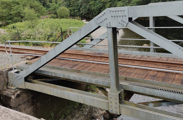
For analysis purposes it is often reasonable to assume that any loads carried by the structure can be modelled as acting at the joints, instead of being distributed over the length of the members. This is usually valid if the members are relatively short.
This means that structures like the bridge shown above can often be analysed as trusses.
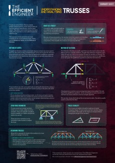
The Efficient Engineer Summary Sheets
The Efficient Engineer summary sheets are designed to present all of the key information you need to know about a particular topic on a single page. It doesn’t get more efficient than that!
Truss stability
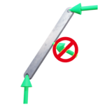
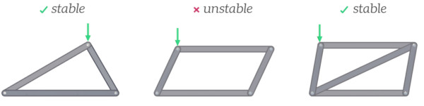
The base shape of a truss is three members connected to form a triangle. If a load is applied to the structure the angles of the triangle won’t be able to change if the length of each of the members stays the same. This means that the triangle is a very stable shape that won’t deform when loads are applied to it, and so it is a great base from which to build a larger structure.
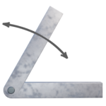
Joining four members together does not form a stable structure. The angles between members can change without any change in the length of the members, so using a four-sided shape as the base for building a truss structure would be a terrible choice. An easy way to stabilize this configuration is to add a diagonal bracing member to split it into triangles.
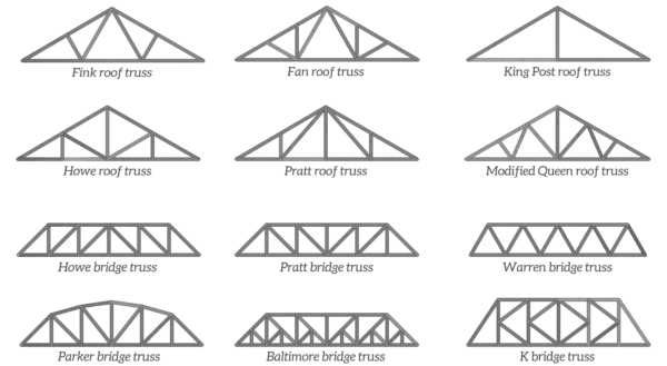
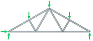
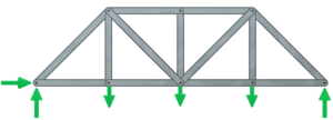
The figure below shows some common truss designs, which as you can see are made up of triangular elements.
Analysing Trusses
When analysing a truss the main objective is to determine the force in each of its members for a certain set of applied loads. This allows us to check that the members can carry the loads without failing, or gives us the information we need to select the best cross-section for each of the members. There are two main methods we can use to do this – the Method of Joints, and the Method of Sections.
The Method of Joints
The method of joints involves applying the static equilibrium equations to the joints in the truss to determine the forces acting on each joint. From there the tensile or compressive axial force carried by each member of the truss can easily be determined.
Here’s how it works:
Step 1
Draw a free body diagram of the truss and solve reaction forces
The first step is to draw a free body diagram showing all of the external loads acting on the truss.
The reaction forces at the truss supports can then be calculated using the three static equilibrium equations.
$$\sum F_\leftrightarrow = 0$$ $$\sum F_\updownarrow = 0$$ $$\sum M = 0$$
Step 2
Draw a free body diagram of each joint and solve internal forces
The next step is to draw a free body diagram for every single joint, and work through them one by one to solve the unknown forces acting at the joint.

The unknown forces can be determined by once again applying the equilibrium equations. All of the joints are pinned connections so there are no moments – you only need to consider equilibrium of the horizontal and vertical forces. $$\sum F_\leftrightarrow = 0$$ $$\sum F_\updownarrow = 0$$
This calculation gives the forces imparted on each of the joints by the members of the truss. The force each member imparts on a joint is equal and opposite to the axial force within the member. If the force acting on a joint because of a specific member is acting away from the joint, it means that the member is in tension, and if the force is acting towards the joint it means that the member is in compression.
Remember that each member is carrying a uniform axial load. This means that if you know the force acting on the joint at one end of the member, the force acting on the joint at the other end of the member will be the same.
The method of joints is useful when you need to calculate the forces in all of the members in the truss, but sometimes you only need to determine the force in one or two members. In this case an alternative method, called the Method of Sections is quicker.
The Method of Sections
When using the Method of Sections, an imaginary cut is made through the truss. Beause the internal forces within the truss members develop in such a way that they balance the external forces (i.e. the reaction forces and the applied loads), the static equilibrium equations can be applied to determine the forces in the members that have been cut through.
Here’s a more detailed summary of the process:
Step 1
Draw a free body diagram of the truss and solve reaction forces
The first step is to draw a free body diagram showing all of the external loads acting on the truss. The three static equilibrium equations can be applied to calculate the reaction forces.
$$\sum F_\leftrightarrow = 0$$ $$\sum F_\updownarrow = 0$$ $$\sum M = 0$$
This is the exact same first step as for the Method of Joints.
Step 2
Cut the truss through the members of interest and draw the internal forces
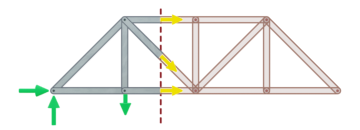
The next step involves making an imaginary cut through the members of interest in the truss, and drawing the internal forces in the cut members.
Step 3
Apply the equilibrium equations to solve the internal forces
The internal forces and external forces will always be in equilibrium, no matter where you have decided to cut the truss. This means that the static equilibrium equations can be applied to solve the internal forces in the cut members.
$$\sum F_\leftrightarrow = 0$$ $$\sum F_\updownarrow = 0$$ $$\sum M = 0$$
The result of the calculation is the axial force in the members that have been cut through.
Related Topics

Shear Force and Bending Moment Diagrams
These diagrams are used to determine the distribution of shear force and bending moments along a beam, accounting for supports and loads.
Area Moment of Inertia
The area moment of inertia describes how the material of a cross-section is distributed relative to a specific bending axis.