Internal stresses develop within any body in response to externally applied loads. At any given point within the body, these internal stresses have components acting in both the normal and the shear directions.
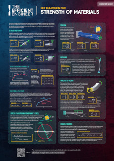
The normal and shear stress components are shown in the image below acting on a 3D stress element that represents a single point within the body. They can also be written in a matrix form, which is called the stress tensor. A tensor is a mathematical object, in this case a 3×3 matrix, that has special properties and is used to represent certain physical quantities, like the stress state at a given point in a body.
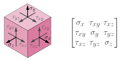
For plane stress conditions the stress tensor is simplified to a 2×2 matrix because the stresses in one of the three directions are close to zero. This is usually a valid assumption for thin objects that are only loaded in the plane of the material.
Stress Transformation
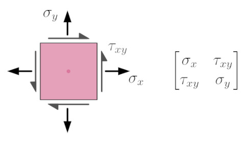
The magnitude of the normal and shear stress components will change depending on how the stress element is oriented. This is illustrated below for a bar under plane stress conditions subjected to uniaxial tension.
If the stress element is oriented as shown in the top part of the image, where it is aligned with the direction of the applied load, then there is only one stress component, a normal stress $\sigma_x$ acting in the $x$ direction – the $\sigma_y$ and $\tau_{xy}$ components are equal to zero. If the stress element is rotated by an angle $\theta$, as shown in the bottom part of the image, the components denoted as $\sigma_{x’}$, $\sigma_{y’}$ and $\tau_{x’y’}$ are now non-zero.
It’s important to understand that the overall stress state at the point of interest isn’t changing as the stress element is rotating. The only thing that is changing is the coordinate system used to observe the stresses.
The equations shown below can be used to compute the stress components for any orientation of the stress element, where $\theta$ is the angle through which the stress element is rotated. The process of determining the normal and shear stress components for different orientations of the stress element is called stress transformation, and as such these are called the stress transformation equations.
The purpose of stress transformation is to obtain the normal and shear stress components acting on a particular plane. There are quite a few different scenarios where you might need to do this. Here are a few examples:
- You might need to determine the normal forces acting on a weld.
- You might be interested in the shear stresses acting on an adhesive joint.
- You might need to determine the largest normal stress for any orientation of the stress element, to predict how and when the material will fail.
What is Mohr’s Circle?
Mohr’s circle is a powerful graphical method used to visualise and analyze the stress state at a single point within a body. It allows you to determine the normal and shear stress components for different orientations of the stress element graphically, instead of using the stress transformation equations.
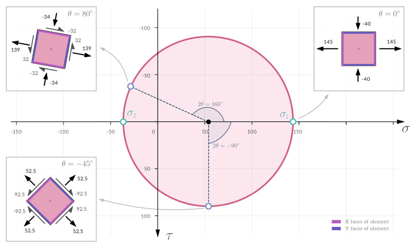
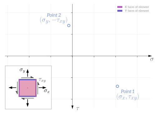
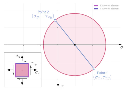
Mohr’s circle is a circle drawn on a graph that has normal stress on the horizontal axis and shear stress on the vertical axis. An example for a plane stress case (i.e. two-dimensional stress) is shown below. Each point on the circle defines the normal and shear stress components for a certain orientation of the stress element. The image shows the stress elements for three different points on Mohr’s circle, corresponding to three different orientations of the stress element.
Mohr’s circle can be used to, for example:
- Easily determine the maximum shear and normal stresses at a single point.
- Determine the principal stresses and the orientation of the principal plane at a single point (more about principal stresses later).
- Develop a more intuitive and complete understanding of the stress state at a single point.
Angles on Mohr’s Circle
An important thing to note is that angles on Mohr’s circle are doubled compared to the angle the stress element is rotated by. For example there is a 90 degree angle between the stresses on the X and Y faces of the stress element. However on Mohr’s circle there is a 180 degree angle between these stresses.
When angles are shown on Mohr’s circle they are often denoted as $2 \theta$. $\theta$ is the angle the stress element is rotated by, and $2 \theta$ is the corresponding angle on Mohr’s circle. In the image above rotating the stress element by an angle of $\theta = 80^\text{o}$ corresponds to an angle of $2 \theta = 160^\text{o}$ on Mohr’s circle.
Sign Convention for Mohr’s Circle
Stresses are usually considered to be positive or negative based on the following sign convention:
- Shear stresses are positive if they tend to rotate the stress element counter-clockwise, and are negative if they tend to rotate it clockwise.
- Normal stresses are positive if they are tensile and negative if they are compressive.
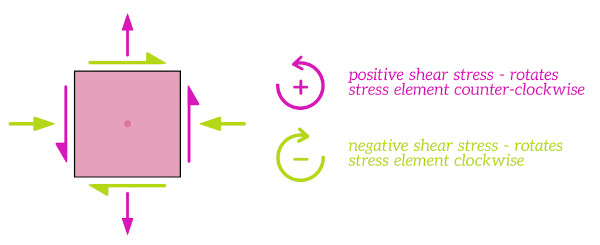
On Mohr’s circle the normal stress component is shown on the horizontal axis and the shear stress component is shown on the vertical axis. The most common convention for the vertical axis is to plot positive shear stresses (i.e. shear stresses that tend to rotate the stress element counter-clockwise) in the downwards direction.
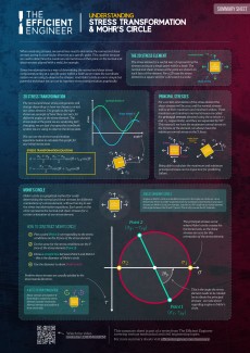
The Efficient Engineer Summary Sheets
The Efficient Engineer summary sheets are designed to present all of the key information you need to know about a particular topic on a single page. It doesn’t get more efficient than that!
Constructing Mohr’s Circle
The video below covers stress transformation and how to construct Mohr’s circle in detail.
To construct Mohr’s circle all you need to know is the normal and shear stresses for one orientation of the stress element. Here are the steps:
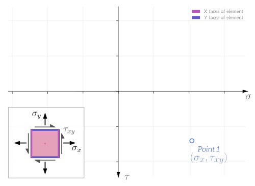
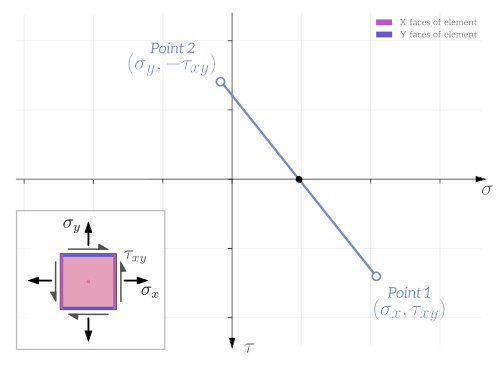
A lot of useful information can be determined from Mohr’s circle, like the maximum shear stress $\tau_{max}$, which is equal to the radius of the circle, or the principal stresses $\sigma_1$ and $\sigma_2$.
Principal Stresses
For certain orientations of the stress element the shear stresses will be zero, and the normal stresses will be at their maximum and minimum values. These maximum and minimum normal stresses are called the principal stresses, and they are denoted as $\sigma_1$ and $\sigma_2$ respectively. If the normal stress is at it’s maximum value on the X face of the element, it will be at it’s minimum value on the Y face of the element, and vice-versa.
It is easy to identify the principal stresses on Mohr’s circle – they occur where the shear stress component is zero, i.e. where the circle crosses the horizontal axis.
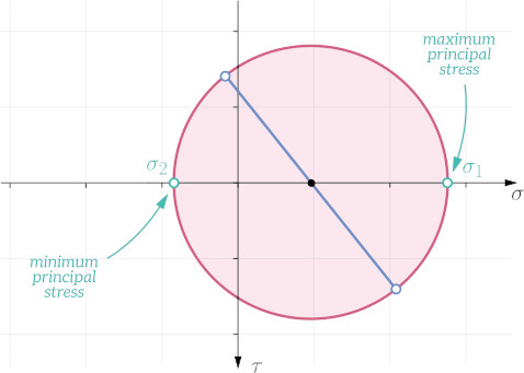
The planes (i.e. the orientations of the stress element) where the principal stresses occur are called the principal planes.
Being able to determine the principal stresses is often an important first step in predicting failure of a material.
Determine the maximum shear stress for the stress state defined by the Mohr's circle shown below.

90.1 MPa
155.1 MPa
0 MPa
220.3 MPa
The maximum shear stress is the lowest point on the vertical axis (postive shear stresses have been plotted in the downwards direction). As can be seen from the image below, this corresponds to 90.1 MPa.

Mohr’s Circle in Three Dimensions
So far we’ve only discussed Mohr’s circle for plane stress conditions, where the stress state is two dimensional. But Mohr’s circle can also be drawn for a more generic three-dimensional stress state, where it is made up of three different circles, as shown below. All possible combinations of normal and shear stresses for the 3D stress element lie on the boundary of, or within, the shaded area.
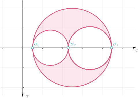
For a three-dimensional stress state there are three principal stresses, which by convention are numbered as follows: $\sigma_3 < \sigma_2 < \sigma_1$.
Mohr’s Circle for Strain
Mohr’s circle can also be applied to strains instead of stresses. It works in exactly the same way, except the normal stresses $\sigma$ and shear stresses $\tau$ are replaced by normal strains $\varepsilon$ and shear strains $\gamma$.
Related Topics

Stress and Strain
Stress and strain are fundamental concepts that relate to the internal forces and deformations within a body in response to applied loads.

Plane Stress
A component is said to be in a condition of plane stress when all of the stresses acting on it are in the same plane.