The area moment of inertia, also called the second moment of area, is a parameter that defines how much resistance a shape (like the cross-section of a beam), has to bending because of its geometry.
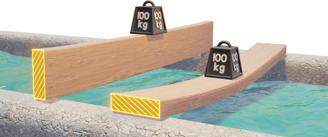
Consider a thin plank that supports a 100 kg load. The plank will be much less stiff when the load is placed on the longer edge of the cross-section. This is because resistance to bending depends on how the material of the cross-section is distributed relative to the bending axis. The plank on the left has more material located further from the bending axis, which makes it much stiffer.
This resistance to bending can be quantified by calculating the area moment of inertia of the cross-section. It is denoted using the letter $I$, has units of length to the fourth power, which is typically $mm^4$ or $in^4$. It reflects how the area of the cross section is distributed relative to a particular axis. It’s not a unique property of a cross section – it varies depending on the bending axis that is being considered.
Let’s compare $I$ values calculated for a few different cross-sections, for the bending axis shown below:
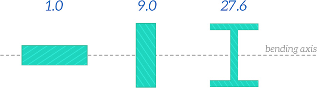
Cross-sections that locate the majority of the material far from the bending axis have larger moments of inertia – it is more difficult to bend them. This is one of the reasons the I-beam is such a commonly used cross-section for structural applications – most of the material is located far from the bending axis, which makes it very efficient at resisting bending whilst using a minimal amount of material.
Area Moment of Inertia vs Second Moment of Area
Both the terms “second moment of area” and “area moment of inertia” are used. Second moment of area is often preferred to avoid any confusion with the moment of inertia, which is a completely different parameter that describes the resistance of a body to angular acceleration, although it is calculated in a similar way.
How to calculate the area moment of inertia
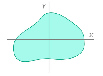
For any arbitrary cross-section like the one shown in the image below, the area moment of inertia can be calculated using this equation:
The $x$ and $y$ subscripts indicate that the area moment of inertia is for for bending about the $x$ and $y$ axes respectively.
Let’s look an example of how this equation can be applied to calculate $I$ for a rectangular cross-section.
Example - Rectangular Cross-SectionWe will use the equation shown above to calculate $I$ for bending about the $x$ axis for the following cross-section:
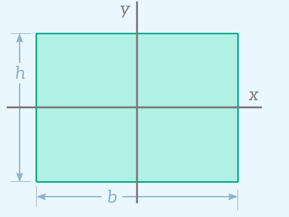
We can think of this rectangular cross-section as being made up of a large number of very thin strips that have a width $b$ and a height $dy$.
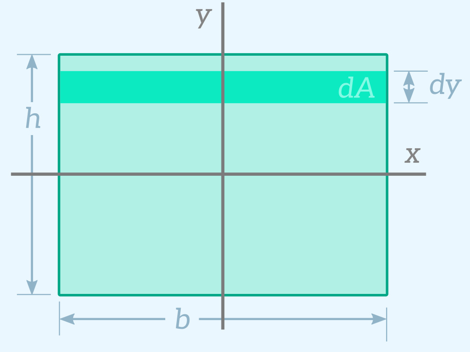
The area of one strip is:
$$dA = b \cdot dy$$$I_x$ is given by the following equation:
$$I_x = \int{y^2 dA}$$Subtituting in the equation for $dA$:
$$I_x = \int{by^2 dy}$$Each strip contributes to the area moment of inertia. This is why we are integrating – to calculate the effect of all of these really small strips. Because the $y$ term is squared, the strips further away from the bending axis (the $x$ axis) contribute much more to $I$ than those close to the axis. To calculate $I_x$ all we have to do is integrate from the bottom of the rectangle at $y = -h/2$ to the top of the rectangle at $y = h/2$.
$$I_x = b\left[ \frac{y^3}{3} \right ]_{-h/2}^{h/2}$$ $$I_x = \frac{bh^3}{12}$$ This gives us the equation for $I_x$. If we repeat the process for bending about the $y$ axis instead, we get the following equation: $$I_y = \frac{b^3h}{12}$$Fortunately you don’t have to go through this process of integrating whenever you need to figure out $I$ for a cross-section and bending axis. If it’s a fairly standard shape you can just look up an equation that has already been derived for your particular cross-section. Most strength of materials textbooks include tables like the one shown below that list $I$ equations for common cross-sections. You can use our area moment of inertia calculator to calculate area moment of inertia values for different cross-sections.
| Cross-Section | Area Moment of Inertia | |
|---|---|---|
| Filled Circle | 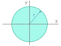 | $$I_x = I_y = \frac{\pi}{4}r^4$$ |
| Hollow Circle | 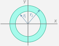 | $$I_x = I_y = \frac{\pi}{4}(r_2^4 – r_1^4)$$ |
| Rectangle | 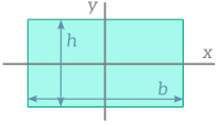 | $$I_x = \frac{bh^3}{12}$$$$I_y = \frac{b^3h}{12}$$ |
The Parallel Axis Theorem
The parallel axis theorem is a really useful theorem that makes it easy to calculate $I$ for different bending axes without having to derive the equation from scratch using the integration method.
It states that the area moment of inertia about any axis $I_x$ can be calculated from the area moment of inertia about a parallel axis $I_{xc}$ that passes through the centroid of the cross-section, the area of the cross-section $A$ and the distance between the two axes $d$.
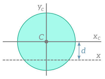
The centroid is the geometric center of the cross-section, or in other words the point at which you would be able to balance the cross-section on a pin.
Reference texts normally provide equations for $I$ for centroidal axes, so the parallel axis theorem is a powerful tool for extending those equations to any other parallel axes.
Adding and Subtracting Area Moments of Inertia
Area moments of inertia can be summed and subtracted to calculate values for composite cross-sections. The image below shows how this technique can be used to calculate $I_x$ for a hollow section.
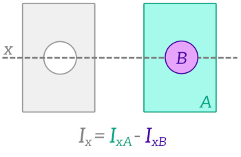
When using this method you need to make sure that the $I$ values for the component cross-sections ($I_{xA}$ and $I_{xB}$ in the example above) correspond to the correct bending axis, or else you will first need to apply the parallel axis theorem to get $I$ values for the correct axis.
Applications of the Area Moment of Inertia
The area moment of inertia is an important parameter for any application that which involves bending of a structural member, which means it appears constantly in the analysis of beams and columns.
Here are a few examples.
$I$ appears in the equation that is used to determine the deflection of a beam for an applied bending moment M.
$$\frac{d^2 v}{dx^2}= \frac{M}{EI}$$$I$ appears in the equation that gives the critical load at which a column will buckle.
$$P_{cr} = \frac{\pi^2 E I}{L^2}$$If you’re interested in learning more about these applications, check out the beam deflection and buckling pages.
As demonstrated by the two examples shown above, the area moment of inertia often appears in equations alongside Young’s modulus $E$. The term $EI$ is given the name flexural rigidity. $I$ represents the stiffness of a beam cross-section due to its geometry, and $E$ represents the stiffness of the cross-section due to its material. The flexural rigidity $EI$ represents the total stiffness of the cross-section.
Polar Moment of Inertia
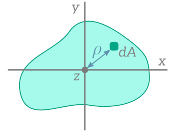
In addition to calculating the area moment of inertia for $x$ and $y$ axes that are in the same plane as the cross-section, we can also calculate the area moment of inertia for an axis that is perpendicular to the cross-section. This is called the polar moment of inertia, and it is usually denoted either using the letter $J$ or as $I_z$. It is often used in problems involving torsional deformation, which is the twisting of a beam or shaft.
$J$ accounts for how the area of the cross-section is distributed radially relative to the rotation or twisting axis $z$. The $\rho$ term is the distance from the $z$ axis (which is pointing out of the screen in the image below) to an element dA.
Like with $I_x$ and $I_y$, the $\rho$ term is squared in the equation, which means that areas of the cross-section that are located far from the axis of rotation contribute most to the value of $J$. This is why transmission shafts are hollow – the central portion of the cross section doesn’t contribute much to the torsional resistance, so it’s more efficient to use hollow shafts.
An interesting observation we can make is that the polar moment of inertia about an axis passing through a specific point on the cross-section is equal to the sum of the area moments of inertia for two perpendicular axes that pass through the same point. This is called the perpendicular axis theorem.
The derivation for this theorem is pretty simple – check out the Understanding the Area Moment of Inertia video if you’d like to see it.
Releated Topics
Trusses
Trusses are structures (e.g bridges or roofs) made up of members that can only carry tensile or compressive axial loads.

Stress and Strain
Stress and strain are fundamental concepts that relate to the internal forces and deformations within a body in response to applied loads.