Understanding Laminar and Turbulent Flow
What is the difference between laminar and turbulent flow?
Laminar and turbulent flow are two regimes that can be observed in a flowing fluid. They behave in fundamentally different ways.
LAMINAR FLOW
The laminar flow regime is characterised by smooth, even flow. The fluid moves in parallel layers and there is a minimal amount of mixing between layers.

TURBULENT FLOW
The turbulent flow regime is characterised by chaotic movement and contains swirling regions called eddies. This results in significant mixing of the fluid. Turbulent flow is more difficult to model and analyse than laminar flow because it is much more chaotic and random.

Because these two flow regimes are so fundamentally different we need a way of predicting which is likely to occur for a particular set of flow conditions. This is done by calculating a parameter called Reynolds number.
Reynolds number
Reynolds number is a dimensionless parameter that was defined by Osborne Reynolds in 1883, and can be used to predict if flow will be laminar or turbulent:
where $\rho$ is the fluid density, $u$ is the flow velocity, $L$ is a characteristic length (see explanation box below) and $\mu$ is the fluid viscosity
Reynolds number gives an indication of the flow regime because it is a measure of the relative significance of the inertial and the viscous forces in the flow.
$$Re = \frac{\mathrm{force_{inertial}}}{\mathrm{force_{viscous}}}$$
Inertial forces are the forces related to the momentum of the fluid – they represent the forces that cause the fluid to move. Viscous forces are the frictional forces that develop between layers of the fluid due to its viscosity.
If viscous forces dominate, meaning that $Re$ is a small number, flow is more likely to be laminar, because the viscous frictional forces within the fluid will dampen out any initial turbulent disturbances and random motion, resulting in laminar flow. But if $Re$ is large, the inertial forces dominate and the viscous forces are too small to prevent chaotic motion of the fluid, resulting in turbulent flow.
The Efficient Engineer Summary Sheets
The Efficient Engineer summary sheets are designed to present all of the key information you need to know about a particular topic on a single page. It doesn’t get more efficient than that!

The transition from the laminar to the turbulent flow regime occurs when Reynolds number reaches a critical value, which will depend on the type of flow being considered. For flow in a pipe the following ranges are typical:
- $Re < 2000$ – laminar flow
- $2000< Re < 4000$ – transitional flow
- $Re > 2000$ – turbulent flow
THE CHARACTERISTIC LENGTH $L$
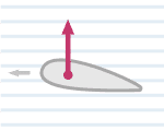
The characteristic length $L$ in the Reynolds number equation will depend on the type of flow being analysed. For flow past a cylinder it will be the cylinder diameter, for flow past an airfoil it will be the chord length, and for flow through a pipe it will be the pipe inner diameter.

Related Topics

Bernoulli's Equation
Bernoulli's equation is an important equation that defines the relationship between velocity, pressure and elevation in a flowing fluid.
Aerodynamic Lift
Lift is an aerodynamic force acting on an object moving through a fluid that acts in the direction perpendicular to the motion of the object.
