Buckling is an important topic that any engineer designing structures that carry compressive loads must understand.
This page will guide you through the basics of buckling, from Euler’s formula for predicting the onset of buckling to more complex topics like slenderness ratios and inelastic buckling. So keep reading, or watch the animated video below, to get up to speed.
What is Buckling?
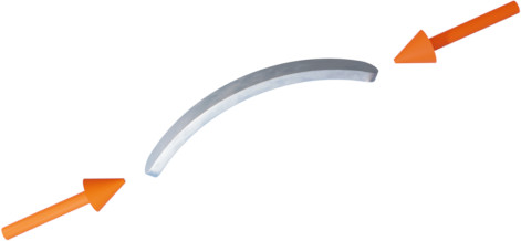
Buckling is the sudden deformation of a structural member that is loaded in compression, that occurs when the compressive load in the member reaches a critical value.
Buckling often occurs suddenly, and can produce large displacements. This doesn’t always result in yielding or fracture of the material, but buckling is still considered to be a failure mode since the buckled structure can no longer support a load in the way it was originally intended to.
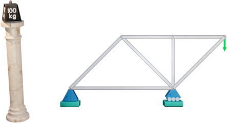
Any long structural member that is loaded in compression is at risk of failing due to buckling. Columns are common examples of structures that may fail by buckling. Individual members in trusses are frequently loaded in compression, so trusses are another example of a structure at risk of failure due to buckling.
Euler’s Buckling Formula
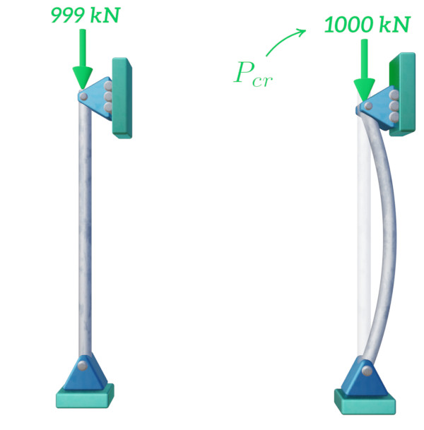
Euler’s buckling formula is a simple equation that is used to calculate the axial load $P_{cr}$ at which a column or beam will buckle. At the critical buckling load any small perturbation, whether it’s a lateral force or a small imperfection in the column geometry, will cause the column to buckle.
The critical load depends on only three parameters, the Young’s modulus $E$ of the column material, the second moment of area $I$ of the column cross-section, and the effective length $L_e$ of the column.
You can use our critical buckling force calculator to see how the different input parameters affect how much force a column can carry.
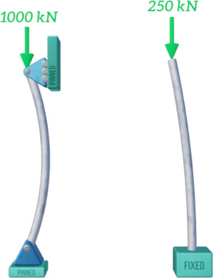
The figure below illustrates how a column with a critical buckling load of 1000 kN will buckle.
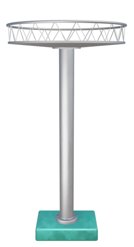
A column is being designed to support a platform, but elastic buckling is a concern. Which of the following proposed options can be used to reduce the risk of buckling?
Choose a material with a lower Young's modulus
Increase the length of the column
Modify the cross-section to increase the second moment of area
Choose a material with a higher yield strength
The Euler critical buckling force is calculated using the following equation:
$$P_{} = \frac{\pi^2 E I}{{L_e}^2}$$
Of the proposed options only modifying the cross-section to increase the second moment of area will increase the critical buckling, and so will reduce the risk of buckling.
Reducing Young’s modulus or increasing the column length will reduce the critical buckling force. And since we are dealing with elastic buckling the yield strength of the material is irrelevant.
Effective Length and End Conditions
The way the ends of a column or beam are restrained will affect the critical buckling load. A column that is fixed at one end and free at the other will clearly only be able to support a much smaller load before buckling compared to one that is pinned at both ends. The buckled shapes are also quite different.
Euler’s formula accounts for different end conditions using the effective length parameter $L_e$.
A column that is pinned at both ends has an effective length that is equal to the length of the column $L$. Other end conditions result in an effective length that is equal to the length $L$ multiplied by a specific factor. These factors are shown in the table below for a few different end conditions.
| End Condition |  |  | 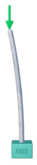 | 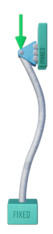 |
|---|---|---|---|---|
| Effective Length | $L_e = 0.5L$ | $L_e = L$ | $L_e = 2L$ | $L_e = 0.7L$ |