Understanding Bernoulli’s Equation
Bernoulli’s equation is a simple but incredibly important equation in physics and engineering that can help us understand a lot about the behavior of fluids. It describes the relationship between the pressure, velocity and elevation of a flowing fluid.
You can watch the video below for an animated introduction to Bernoulli’s equation, or just keep reading to learn more.
Bernoulli’s equation is essentially a statement of the conservation of energy. It tells us that the static pressure (how much the fluid is pressurised), the dynamic pressure (how fast the fluid is moving), and the hydrostatic pressure (how high up the fluid is) of the fluid remain constant along a streamline.
Here is the equation, which was first published by Daniel Bernoulli in 1738.
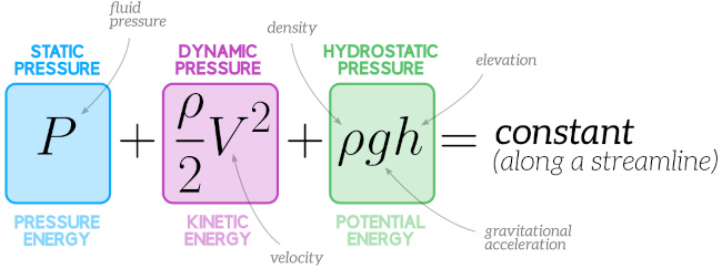

The equation reflects the idea that energy is conserved along a streamline because the three terms can be thought of a representing the pressure energy, kinetic energy and potential energy of the fluid. Bernoulli’s equation states that the overall sum of these energies doesn’t change along a streamline – the energy of the fluid is just transferring between these different forms. If the elevation of the fluid increases, for example, the pressure or the velocity must reduce in proportion.
In the real world energy isn’t completely conserved – some energy will always dissipate as a fluid flows, because of the viscosity of the fluid. Energy conservation is one of several assumptions that is built into Bernoulli’s equaton. We’ll cover some of the other assumptions later on.
What is a streamline?
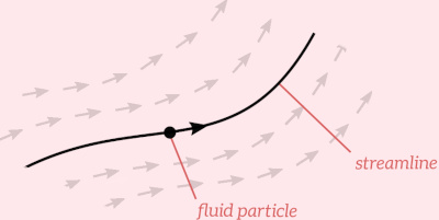
Bernoulli’s equation states that the static, dynamic and hydrostatic pressures are constant along a streamline. But what’s a streamline?
In steady flow (flow that doesn’t vary with time), a streamline is defined as the path traced by a single particle within the fluid.

Bernoulli’s equation is usually applied to compare the flow conditions between two points on the same streamline, in which case it is written like this:
$$P_1 + \frac{\rho_1}{2}{V_1}^2 + \rho_1 g h_1 = P_2 + \frac{\rho_2}{2}{V_2}^2 + \rho_2 g h_2$$
Why is Bernoulli’s equation useful?
Bernoulli’s equation helps us understand how the pressure, velocity and elevation of a fluid are linked. We can use it to calculate the velocity of water exiting a hose, or to figure out if there is a risk of cavitation (low pressure) in a piping system, for example. It does make some simplifying assumptions, but it is a very powerful tool.
The Efficient Engineer Summary Sheets
The Efficient Engineer summary sheets are designed to present all of the key information you need to know about a particular topic on a single page. It doesn’t get more efficient than that!


Example – Hosepipes and Venturi Meters
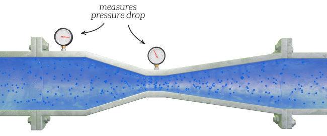
Let’s look at an example where we apply Bernoulli’s equation to flow through a restriction in a water hosepipe. The objective is to calculate the change in pressure between Point 1 and Point 2, which are on the same streamline.
$$P_1 + \frac{\rho_1}{2}{V_1}^2 + \rho_1 g h_1 = P_2 + \frac{\rho_2}{2}{V_2}^2 + \rho_2 g h_2$$


The difference in elevation between the two points is negligible ($h_1 = h_2$), so we can remove the elevation terms from Bernoulli’s equation, and re-arrange obtain this equation for the difference in pressure between the two points.
$$P_1 – P_2 = \frac{\rho}{2}({{V_2}^2 – V_1}^2)$$
The fluid is incompressible, so the mass flow rate between points 1 and 2 must be the same:
$$\dot{m}_1 = \dot{m}_2$$
$$\rho A_1 V_1 = \rho A_2 V_2$$
By re-arranging we can see that the velocity at point 2 is equal to the velocity at point 1 multiplied by the ratio of the areas of the pipe at the two points.
$$V_2 = \frac{A_1}{A_2}V_1$$
Substituting this equation into the pressure difference equation gives us an equation for the pressure change based only on $V_1$, $A_1$, $A_2$ and the fluid density $\rho$.
$$P_1 – P_2 = \frac{\rho}{2}{V_1}^2(\frac{{A_1}^2}{{A_2}^2}-1)$$
Because of the restriction $A_2 < A_1$, which means that the velocity increases between Point 1 and Point 2 but the pressure decreases.
The Venturi meter is a flow measurement device that works on this principle – it measures the pressure drop across a converging section of pipe ($P1 – P_2$), and applies Bernoulli’s equation to calculate the fluid flow rate.

Bernoulli’s Principle
As we saw in the example above, Bernoulli’s equation tells us that if you restrict the flow of water through a hosepipe, the velocity of the water will increase as it passes through the restricton, but the pressure of the water in the restricted section will drop.
This might seem counter-intuitive – it feels natural to assume that an increase in velocity results in an increase in pressure, but it makes sense when you think about the conservation of energy. The energy needed to increase the velocity of the fluid comes at the expense of the pressure energy.
This is an interesting observation that we can derive from Bernoulli’s equation – for horizontal flow (i.e. when there is no change in the elevation term) if there is an increase in the velocity of the fluid, there must be a decrease in pressure. This observation is known as Bernoulli’s Principle.
The different forms of Bernoulli’s equation
Bernoulli’s equation can be stated in three different forms, depending on whether each term has units of energy, pressure or distance. The form of the equation shown at the top of this page was the pressure form.
These forms of Bernoulli’s equation are saying the same thing – that energy is conserved along a streamline. They are just using different quantities to express this concept. Which form of the equation you should use depends on what it is you are trying to calculate (energy, pressure or head).
Bernoulli’s equation assumptions
Bernoulli’s equation is based on a few assumptions that it’s important to understand to be able to apply it correctly:
- Inviscid flow – Bernoulli’s equation assumes that the fluid is inviscid, meaning that it has no viscosity. If the fluid is viscous there would be some dissipation of the fluid’s internal energy as it flows, and the idea that energy is conserved along a streamline would not apply. Of course no fluid is truly inviscid, so some judgement needs to be used when deciding if the equation is applicable.
- Laminar and steady flow – Bernoulli’s equation can only be used if the flow is steady (i.e. it doesn’t vary with time), and it is laminar. The equation is not applicable for turbulent flow. We’ve got a page covering laminar and turbulent flow if you’d like to learn more about these two flow regimes.
- Incompressible flow – Bernoulli’s equation assumes that the fluid is incompressible. This assumption is usually valid for liquids, but might not be for gases, particularly at high velocities.
Related Topics
Laminar & Turbulent Flow
Laminar and turbulent flow are two fundamentally different flow regimes that can be observed in a flowing fluid.
Viscosity
Viscosity is a measure of the resistance of a fluid to flow, and is defined as the ratio of shear stress to the rate of shear strain in a fluid,


